#2: Hexagonal Tilemap Generation
Terry
This article covers my process on:
- Generating a single mesh from a 2D painted tilemap terrain
- Creating a shader that uses vertex blending to smoothly combine all the different types of terrain
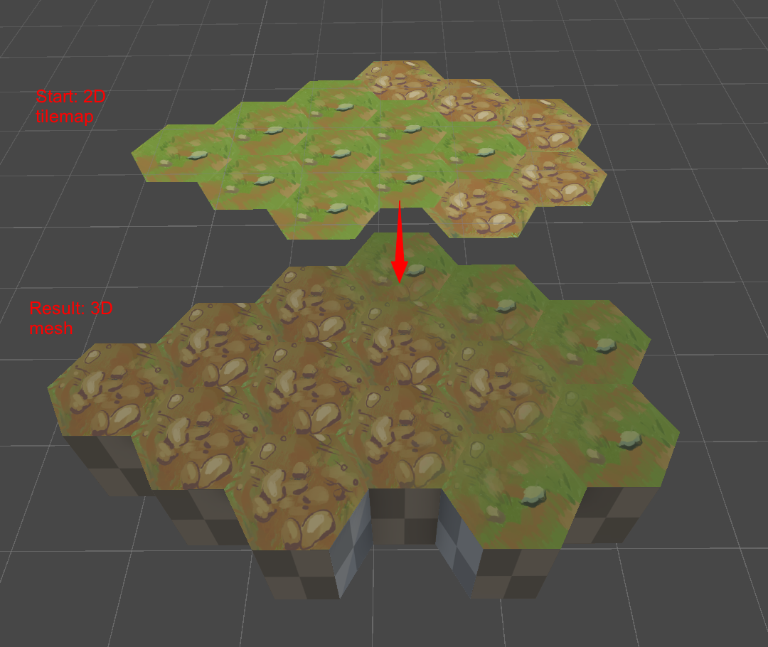
From 2D Tiles to 3D Mesh
Medstrat’s battle gameplay will take place on a 3D grid. It’s entirely possible to model that grid by hand in any modeling program, but what if we want to box something out for some quick reiteration?
Since Unity already has a tile system, I started with that. I use hexagons here but the method can work with your average 4-sided grid or any shape with the right tweaks as long as it tessellates.
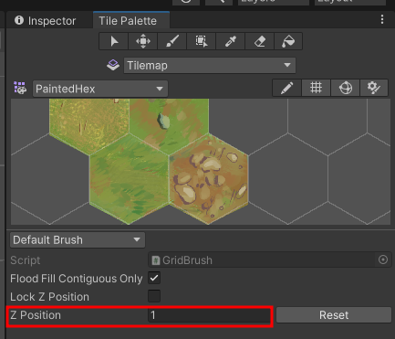
I just painted out the hexes with your average brush. The sprites themselves are sized a little awkwardly but that doesn’t matter too much here. Notice that more than one texture is painted. The way my system is set up, the height of the hex is based on the Z-axis in which it is painted in. All of the tiles in the image shown have a Z value of 1.
I only need to generate terrain on the editor side, so I don’t waste too many resources generating it at runtime. Besides, this tool is meant to create a mesh to start out with, which will go through refinement by an actual 3D artist
To allow me to run this code in the editor, I created a custom editor for the Grid component. It draws the standard UI, but then adds a slot to input a Material, and also a new button to click for when I want to generate the terrain.

Now let’s start with generating that geometry. Instead of going line-by-line in code, I’ll go through my thought process on making the generation. I’ll attach my script at the bottom though for anyone who might find it helpful though.
Every cell in a Tilemap has its own coordinates that describe its location within the grid. These coordinates are different from its worldspace position. You can get them for traversal at myTilemap.cellBounds.allPositionsWithin. As you can see, all of the coordinates are integers.
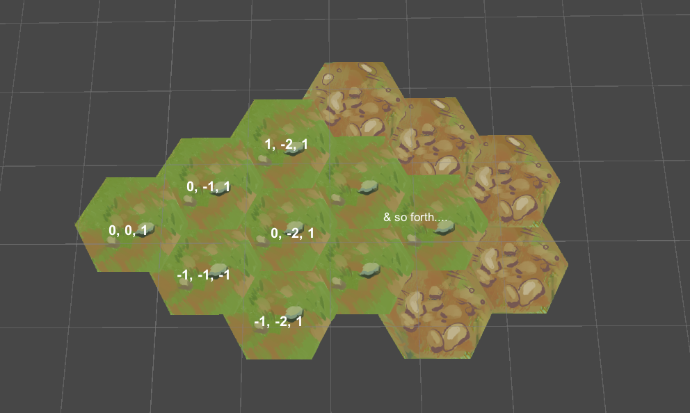
The height of a tile is determined by its local Z Position within the tilemap. In this example, as mentioned before, all of the tiles have a height of 1. A Z value of 0 basically means zero height. So, if you want to vary the heights of your tiles, change the Z Position. Imagine that each tile sprite represents the top face of one hex.
Now to actually generate the mesh.
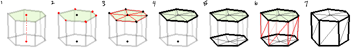
1. Starting from the tilemap, we already have the point that is the center of the top face. The center of the bottom face would be the same position, but with a Z-axis value of 0.
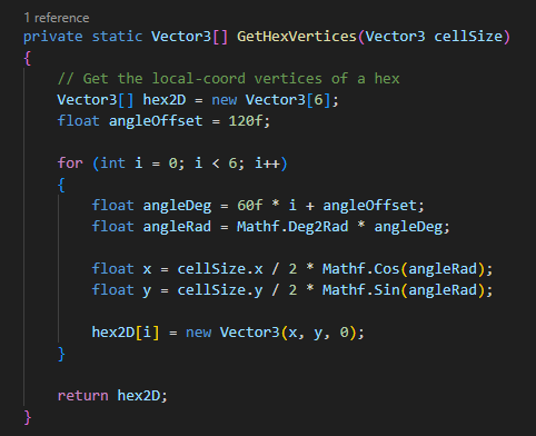
2. With the top center vertex, we generate the positions of the 5 vertices that make up the top face. Extend the first new vertex out by your radius, and then continuously increase the angle offset by 60 degrees until you’ve come full circle. Make sure that all of your faces always wind in the same direction.
3. Now that you have the vertices, you can define the triangles that they create. All triangles are made up of the center vertex, an edge vertex, and the next vertex after that one. Once you reach the last vertex, its partner will be the first vertex again.
4. Set the triangles.
5. Do steps #2-4 for the bottom face.
6. Each side wall is made up of 2 triangles. These also must wind in the same direction as before. However, do NOT set a wall if that edge is on the interior and is next to another hex.
7. Complete. Don’t forget to calculate the Normals and UVs!
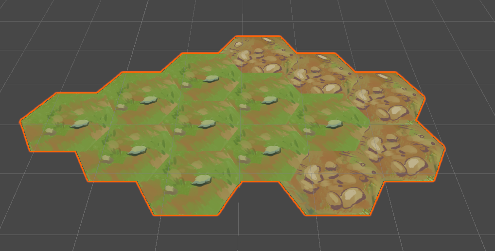
Vertex Colors for a given vertex will either be fully Red, Green, Blue, or Clear. Which color is dependent on the unique texture sprite used in the tilemap for that hex. This means that this method only can support up to 4 different textures to display at once.
Vertices that sit on the border between two differently textured hexes will have their vertex color interpolated. Since the shader uses vertex colors to determine what texture to apply to a face, naturally these borders will appear to have a smooth transition from one terrain to another
(If more than 4 top-face textures is important for your project, you’ll just need to forego interpolation. You could probably fit more than 1 texture inside the definition of a color channel, but 4 is more than enough for my needs. Let me know if you figure out how to do that - I’d love to see it.)
This is my code that is executed on each of the tilemap cells:
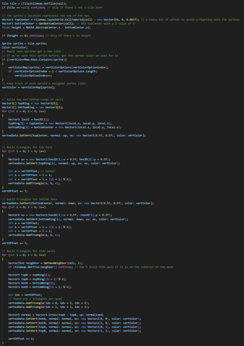
hex2D refers to the output of a helper function that returns a stencil of a 2D hexagon in local space. Then, you can use the stencil to get the positions of the vertices of a hexagon centered anywhere. It makes Step #2 easier to handle.
The variable vertOffset helps with keeping track of where in the overall list of vertices we are currently at. At each tile, an individual hex will always have its first vertex in index 0 of its list, but when considered for ingestion the final single mesh, it can be at any arbitrary index in that massive list.
VertexData is a custom class that holds all of the data we’ve been collecting. It holds the positions of vertices, normal vectors, UVs, vertex colors, and triangles that will be set in our final mesh
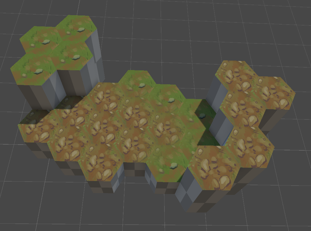
Once it’s done, you should have a single hexagon mesh made from the tiles! It will probably be a bright magenta if it doesn’t have a material applied to it.
Multi-Terrain Shader
Now we build the single shader used for this one piece of geometry we just generated. The shader differentiates faces on two key axes: its vertex color & its normal vector. This is because a single terrain needs to have the texture you see right on top (e.g., grass), and another texture for any other direction (e.g., subterranean dirt).
Essentially, all of the axes on both vectors have their value taken and used as weights multiplied by their respective textures. The result is then linearly interpolated between all of them to produce the end result.
        weightedR = vertexColor.r * texture0
        weightedG = vertexColor.g * texture1
        weightedB = vertexColor.b * texture2
        weightedA = vertexColor.a * texture3

        weightedRG = lerp(weightedR, weightedG)
        weightedBA = lerp(weightedB, weightedA)
        weightedRGBA = lerp(weightedRG, weightedBA)

        weightedX = normal.x * texture4
        weightedY = normal.y * texture5
        weightedZ = normal.z * texture6

        weightedXY = lerp(weightedX, weightedY)
        weightedXYZ = lerp(weightedXY, weightedZ)

        baseColor = lerp(weightedRGBA, weightedXYZ)
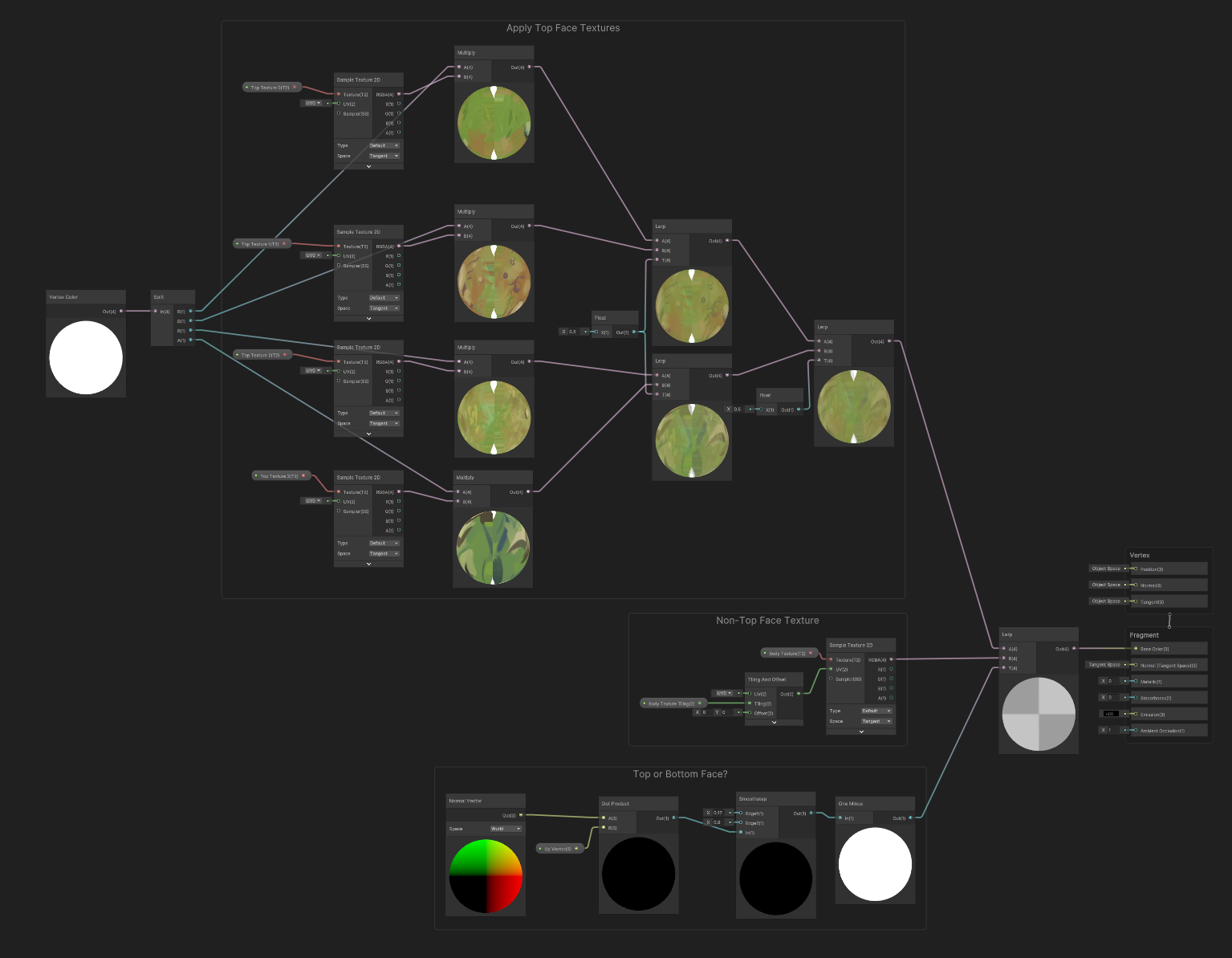
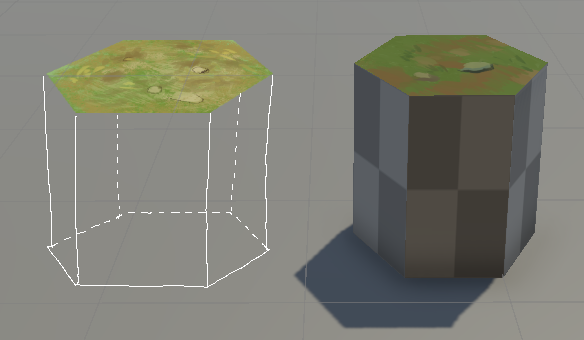
For my demonstration, I have multiple top-facing textures but I’m using only one texture for the other faces (the gray checkerboard pattern). If you want multiples of these, set it up the same way as the top textures.
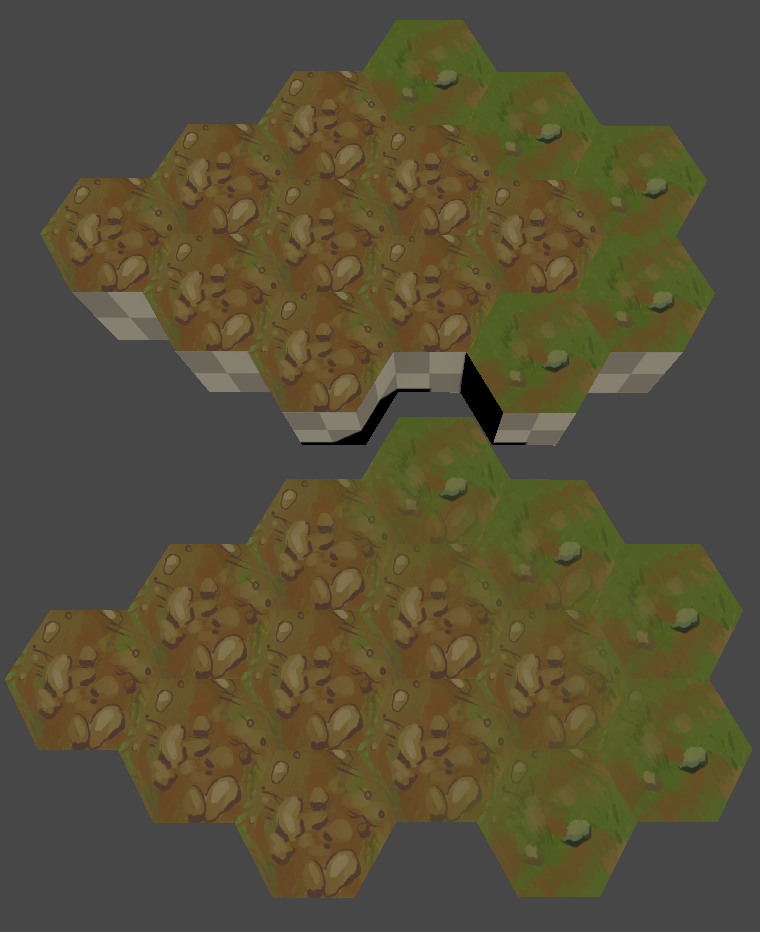
Terrain without (top) and with (bottom) vertex blending. Notice how the edges between the different textures are harsher and smoother, respectively.
Conclusion
Vertex-weighted textures are already a common practice in terrain generation, but I couldn’t find anything that perfectly matched my use case, and also thought it would be a fun learning experience.
Creating individual meshes with their own materials at that, even though it would be easier, is far too intensive for my taste. This method in Unity is still not perfect, but I hope someone out there finds it helpful, or at least an interesting read.
Stay tuned for more adventures, both here and in our game Medstrat :D
Terry
 Download TerrainGenerator.cs
<==
Download TerrainGenerator.cs
<==